Structure is enclosed by building sandwich panels with pressed non-combustible insulation, which complies with fire safety standards. Block-box is equipped with fire and security alarm system. Blocks are provided with local and remote measurement of process parameters. Unit equipment is controlled via automatic control and regulation station system.
Climatic type is determined depending on the construction region.
Advantages
- block-modular design and maximum level of prefabrication allow to install equipment in a short time;
- Easy and flexible process control;
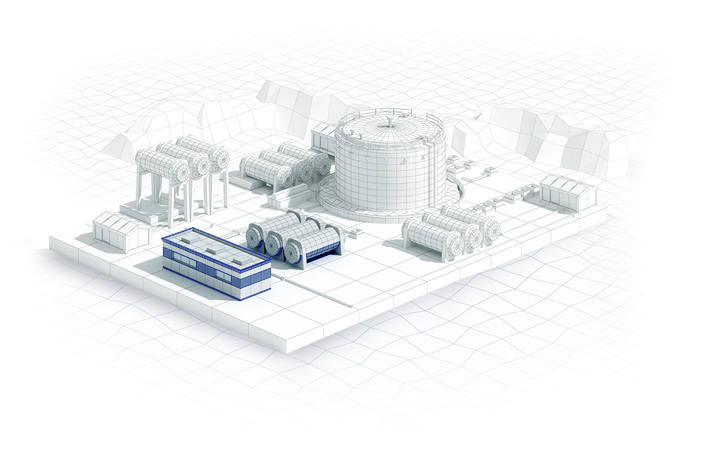
- Unit compactness, all FIGTU equipment is placed in a single mono-block, which allows to reduce construction site and minimize construction and installation works resulting in decrease of capital and operating expenses of the Client.
Scope of Equipment
FIGTU generally includes:
- gas purification unit from liquid and mechanical impurities;
- impulse gas drying unit;
- gas heating unit;
- fuel gas reduction unit for the own needs of compressor station;
- gas metering unit (metering station);
- automated control system unit which can communicate with ACS of compressor station to transmit information and receive control commands.
Operation principle
FIGTUs are designed to treat and supply gas with required characteristics and quality to consumers of compressor yard (compressor station) located at the site.
Gas from inlet header enters gas treatment unit (filter-separators), which includes at least two vessels operating in parallel.
Content of impurities is determined in Client’s Technical Specification.
Gas flow metering unit is designed to measure gas flow through FIGTU, consumed for the own needs of compressor station. Metering unit consists of two lines: operating and by-pass. Metering unit is equipped with gas flow meter foreseen for commercial metering of gas consumption for the own needs of compressor station.
Gas flow measurement margin shall not exceed ±1%.
If necessary, gas enters the gas supply pipeline to gas heaters in order to heat the fuel gas before reduction and ensure the required gas temperature range at the gas compressor inlet. Gas is heated through the intermediate heat transfer agent.
Fuel gas is reduced to a pressure determined by the type of gas compressors used at compressor station. Provision is made for installation of two trains (operating and standby). Two reduction trains ensure guaranteed gas supply of the required pressure to gas compressor. In normal mode gas is supplied by one of the reduction trains, the second train is in standby mode.
Impulse gas treatment unit is intended for treatment of impulse gas for control of pneumatically actuated valves of compressor station and connection assembly. Unit provides for impulse gas drying at dew point down to minus 55 ℃. Unit is delivered as single block complete with automation and control system. Unit parameters are monitored and controlled by FIGTU ACS.
Technical characteristics
| Parameter name |
Value |
| Inlet gas pressure, MPa |
from 0.6 to 16 |
| Outlet gas pressure, MPa |
from 0.001 to 7.5 |
| Throughput capacity (3 standard sizes), st. m3/h: |
500 to 10000; |
| 500 to 20000; |
| 500 to 30000 |
| Fluid |
Natural gas, associated petroleum gas or other gases |
| Inlet gas temperature, °C |
from minus 60 to plus 45 |
| Outlet gas temperature, °C |
from minus 60 to plus 130 |
| Climatic types as per GOST 15150-69 |
У1, УХЛ1, ХЛ1, У2, Т1 |